Connecting the Bat Listener to an Arduino
Posted by Matthew Little on
If you would like to take your bat detecting further, the new version of our Bat Listener has output pads for connecting the output to an Arduino.
This means we can measure the exact frequency and start to do more interesting things like recording the frequencies, displaying a 'sonograph' of the detected signal and record the number of bat detections.
An Arduino is a small micro-controller which can be easily re-programmed to perform different functions. It can also be used as a link to receive data onto a computer. It is an open-source design with an open-source integrated development environment (IDE) and has a huge user-base with millions of examples - definitely worth checking out if you do not know about it already!
In this post I show how I connected the Bat Listener to an Arduino and display accurate frequency data. I am using an Arduino Uno in this example.
You will need:
- Fully built and tested Bat Listener
- Arduino Uno
- Wire
- Soldering iron and tools
The connections are made to the "uP o/p" connector pads - this stands for "micro-processor output". The output has protection diodes to ensure the output voltage is a maximum of 5.1V, so you will not damage the input to the Arduino (which has a maximum input of 5.5V).
We need to solder two wires to these two pads. The circular pad is the ground connection and the square pad is the data connection.
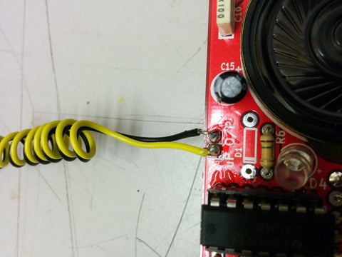
When I did this initially I did not get a high enough voltage on the output to trigger the Arduino. I needed to change the resistor R6 to 10k (rather than the 100k supplied). This must be updated for all future kits!
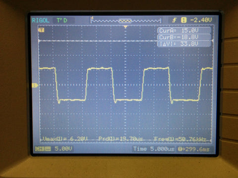
When these two wires are connected you can look at the signal on an oscilloscope, if you have one available. It should show a frequency pulse train in the region of 2-3V high.
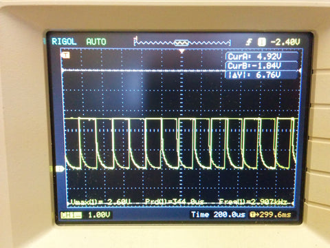
Not a great photo, but shows waveform is around 2.6V high, enough to interrupt the Arduino pin.
I set up an ultrasonic transmitter connected to a variable frequency generator. This meant I could adjust the frequency and so do some accurate testing. I set the frequency to around 50kHz, so out of audible range, but detectable by the Bat Listener.
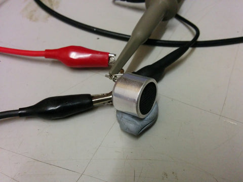
This is a 40kHz ultrasonic transmitter with a 1k resistor in series to limit the current. It works best from 30-50kHz, but fails to do higher frequencies.
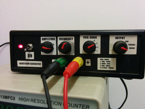
I used this frequency generator (yes - a homebrew design built around 20 years ago!) to control the frequency to the transmitter.
The output waveform from the Bat Listener is generated AFTER the divide by 16 in the circuit. This means to get the actual frequency you need to multiply the measured waveform frequency by 16 to get the real frequency detected.
We need to measure the pulses using a simple arduino code:
/********************************************************
/****** Bat Listener Frequency Measurement **************
/****** by Matt Little **********************************
/****** Date: 10/01/2017 ********************************
/****** hello@curiouselectric.co.uk *********************
/****** www.re-innovation.co.uk *************************
/********************************************************
See www.curiouselectric.co.uk for information and construction details
/*************Details of Code*****************************
This code has been written to measure the frequency from the bat listener.
Bat listener is available from:
https://www.curiouselectric.co.uk/collections/featured/products/bat-listener-2016
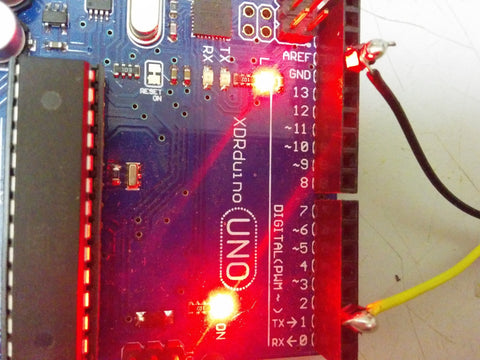
The O/P Terminals are connected to GND and D2 of an Arduino Uno.
D2 is also the interrupt pin.
Each time the pulse arrives then a counter is incremented
Every 1 second this is displayed on the serial output and converted into a frequency.
Pulses per second are converted to the actual frequency, as there is a divide by 16 in the circuit.
Updates:
10/01/2017 Code written - Matt Little
**********************************************************************************************************/
// Variables for the Pulse Counter
int batinterrupt = 0; // Pulse Counter Interrupt - This is pin D2 of arduino - which is INT1
long int pulsecounter = 0; // Holds the number of pulses
long int previousMillis = 0; // Holds the previous millis value for timing
int sampleTime = 1000; // This is the sample period in milliseconds
//****************INITIALISE ROUTINE******************************
void setup()
{
Serial.begin(115200); // Set up a serial output for data display and changing parameters
attachInterrupt(batinterrupt, pulse, RISING); // This sets up our Interrupt Service Routine (ISR) for flow
}
//*********** The flow interrupt**************
void pulse()
{
// Increment the pulse counter
pulsecounter++;
}
void loop()
{
if(millis()>=(previousMillis+sampleTime))
{
previousMillis = millis();
Serial.println(pulsecounter*16);
pulsecounter = 0; // Reset the pulse counter
}
}
This uses an interrupt to accurately count the pulses. The pulses measured in a 1 second (1000 milli-second) sample are multiplied by 16 and printed on the serial port.
Here we can see the input pulses measured using a 'scope:
And here is the data received:
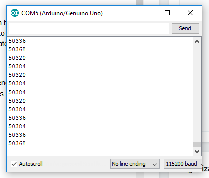
We can see that the 50kHz (approx) signal is accurately measured by the detector.
This is the first test done - once we have the data into the Arduino we can do many more interesting things, such as displaying the data on a small screen, showing a 'sonograph' of the signal and even detecting which species of bat. I will follow this post up with more experiments as they are performed.
Hopefully this post helps you take you bat listener kit further!
Share this post
- 0 comment
- Tags: experiment, kits, new
0 comment